



![[알씨뱅크] I2C-INA-BM [Matek] 고정밀 전압 전류 측정 파워 모듈](/shop/data/goods/fm96244_1792409761.jpg)
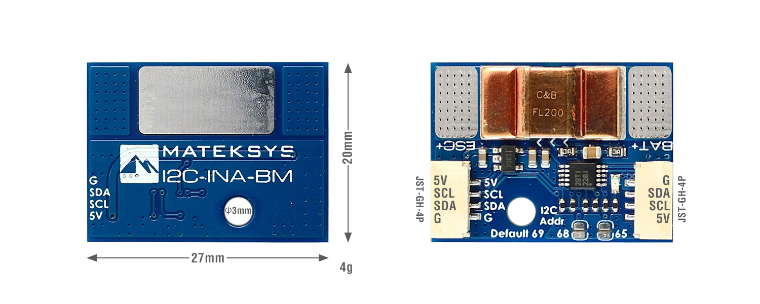
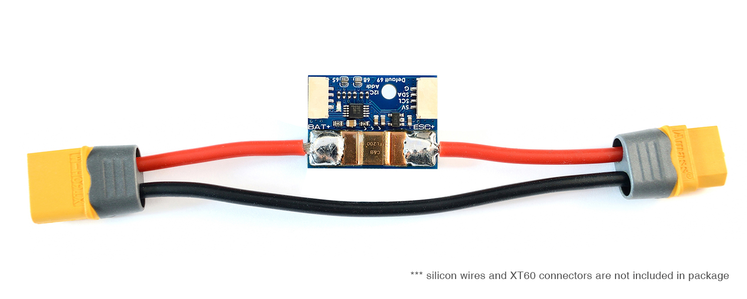
[Matek] 고정밀 전압 전류 측정 파워 모듈
상품번호 QQ96244Ultra-Precise I2C Power Monitor, I2C-INA-BM
제품코드 : I2C-INA-BM
상품번호 : QQ96244
Ultra-Precise I2C Power Monitor, I2C-INA-BM
재입고 알림
 실시간 문의 (오전10시~오후6시)
상품상세설명
기본정보
상품후기
상품문의
판매가격
18,500원
회원할인가격
18,500원
적립금
180원
제품코드
I2C-INA-BM
상품번호
QQ96244
제조사
Matek
배송비
3,500원 (50,000원 이상 무료배송)
배송 안내한진택배 · 50,000원 이상 무료배송
- 알씨뱅크는 빠르고 안전한 한진택배를 이용합니다.
- 총 결제금액이 50,000원 이상인 경우 무료배송으로 발송됩니다. (항공합판, 비행기 등 부피가 큰 상품들은 추가 배송비가 발생합니다.)
- 기본 배송비는 3,500원 입니다. (택배사가 지정한 도서,산간,오지 일부지역은 배송비가 추가됩니다)
- 추가배송비 : 제주도 3,000원 / 기타도서 3,000원
- 네이버페이는 제주, 기타도서 추가 배송비가 자동으로 결제되지 않기 때문에 무통장입금으로 추가결제 해주셔야 합니다.
- 조립이 필요한 상품의 경우 일반 상품보다 배송이 다소 늦어질 수 있습니다. (자세한 배송일정은 고객센터로 문의하시기 바랍니다.)
- 구매대행 또는 예약상품의 경우 해외 배송기간이 추가되며 기간은 상품 및 시기에 따라 차이가 있을 수 있습니다.
- 구매대행 또는 예약상품과 같이 구매한 경우 모든 상품들이 준비된 후 일괄 발송됩니다.
- 국내 재고 상품의 평균 배송일은 입금 확인 후 1~3일입니다. (택배사 사정에 따라 1~2일 지연될 수 있습니다.)
- 출고 마감 시각은 상품마다 다릅니다. 위쪽 재고 상자의 「오늘 00:00 까지 결제하시면 … 출고됩니다」 안내를 확인해 주세요. (주문 수량에 따라 달라질 수 있습니다.)
- 토요일에도 택배를 받아보실 수 있습니다. (일부 지역에 따라 차이가 있을 수 있습니다)
- 토, 일요일 및 공휴일은 택배 발송을 하지 않습니다.
교환 및 반품안내받으신 날부터 7일 이내
- 단순 변심 또는 주문 실수로 인한 상품 청약철회 가능기간은 상품 수령일로 부터 7일 이내 입니다.
- 상품 개봉후 사용하여 상품 가치 훼손 시에는 7일 이내라도 교환 및 반품이 불가능합니다.
- 배터리류는 소모품으로, 제품 박스(포장)를 개봉하면 상품 가치가 현저히 떨어지므로 교환 및 반품이 불가능합니다(제품 하자·오배송 제외).
- 단순 변심 또는 주문 실수로 인한 교환, 반품은 고객께서 왕복 배송비를 부담하셔야 합니다(제품의 하자, 오배송 제외)
- 상품 파손 및 하자에 의한 교환 또는 반품의 배송비는 알씨뱅크에서 부담합니다.
- 제품을 수령하신 후 7일 초과시에는 제품 불량시 초기 불량으로 처리되지 않으며, 제품에 따라 유상 수리 처리됩니다.
- 조립이 필요한 상품의 경우 조립 및 사용의 흔적이 있는 경우 교환 및 환불이 불가능합니다.
- 교환 및 반품시 주소 : 부산광역시 부산진구 연지로13번길 4, 202호 알씨뱅크
관련상품